Contrib icoStructFoam
Contents
1 Description
This solver is a hybrid of icoFoam and stressedFoam. One grid-region is an imcompressible fluid, the other is a solid. The pressure of the fluid is used to deform the solid.
This solver is only a demo. It should not be used to simulate the real world
Ah. And by the way: it does not work in parallel
2 Algorithm
At each time-step the following things are done:
- the equations in the fluid region are solved
- fluid pressures at the fluid/solid-interface are written as boundary equations to the solid
- the equations for the solid are solved
- displacements for the interface-nodes of the solid region are written to the interface-nodes of the fluid region
- the grid of the fluid region is deformed
3 Usage
Due to the two grids the standard Utilities for pre- and post-processing (FoamX and paraFoam) can't be used. Everthing is setup with the help of a text-editor.
In order for blockMesh to work on the grid regions you've got to fool it:
ln -s region1/polyMesh/ icoStructFoamTest/constant/polyMesh
blockMesh . icoStructFoamTest
rm icoStructFoamTest/constant/polyMesh
ln -s region2/polyMesh/ icoStructFoamTest/constant/polyMesh
blockMesh . icoStructFoamTest
rm icoStructFoamTest/constant/polyMesh
To write the data of the two regions for paraview just use foamToVTK:
foamToVTK . icoStructFoamTest -mesh region1
foamToVTK . icoStructFoamTest -mesh region2
An alternative approach is described in How to postprocess multiple regions.
The fluid mesh is deformed. The solid mesh has to be deformed while post-processing (with the Warp (vector) filter)
4 Example cases
Please note that none of these cases resembles anything from the real world and only server for demonstration purposes
4.1 Deformable channel
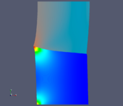
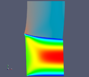
This case simulates flow in a channel. One wall of the channel is coupled to a deformable solid.
The two regions are:
- Lower Region: channel with velocity inlet on the left and pressure outlet on the right
- Upper Region: solid which is fixed at the top and free at the left and the right
In the beginning both of them are of equal size and square.
Due to the higher pressure at the inlet the solid gets deformed.
Both pictures are from the end of the simulation. For the solid the strain is shown. For the fluid the left picture the colors show the pressure, the right picture shows the velocity.
4.2 Soft thing on a stick
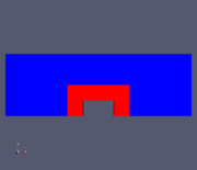
This case simulates the flow through a channel with an obstacle that consists of two parts: a solid, fixed part around which a deformable material is wrapped.
The two regions are shown in the picture on the left:
- Blue: the fluid. On the left-side a velocity inlet, on the right side a pressure outlet. Top is a wall, botto, a symmetry boundary.
- Red: the solid. The bottom edges are symmetry boundaries. The inner edges are fixed (the stick in the title)
The picture on the left is the undeformed geometry at the beginning. The picture on the right is the geometry at the end of the simulation. The solid is colored with the strain, the fluid with the pressure.
In certain parts of Austria this is also known as the Lentos-case.
5 Download
Case of the deformable channel
Case of the soft thing on a stick
6 History
- 11 Nov 2005: Initial upload
- 10 Nov 2006: Changed Version for 1.3
--Bgschaid 13:34, 11 Nov 2005 (CET)


