Getting started with chtMultiRegionSimpleFoam - planeWall2D
Contents
1 Introduction
This page is meant to help the user get started with the chtMultiRegionSimpleFoam and chtMultiRegionFoam solvers. This page is no where near complete, so feel free to add examples based on this planeWall2D example case and write instructions and/or tips on how to use these solvers.
This page began as a result from the discussion help here: chtMultiRegionFoam--unequal temperature at coupled patches - there you might find some very more precious hints on what you can do with these solvers!
Keep in mind that:
- chtMultiRegionSimpleFoam is a
-
Steady-state version of chtMultiRegionFoam
- chtMultiRegionFoam is a
-
Combination of heatConductionFoam and buoyantFoam for conjugate heat transfer between a solid region and fluid region
Note: this case will also work with ![]() , if you do the necessary tweaks in the fvSchemes files of the attached example case.
, if you do the necessary tweaks in the fvSchemes files of the attached example case.
2 planeWall2D - Case description
This is basically the example shown in the book Fundamentals of Heat and Mass Transfer by Frank P. Incropera et. al, chapter 3, section 3.1 "The Plane Wall".
(It's missing a picture, because we can't use the one from the book and I didn't have the time to draw one... -- Wyldckat (talk) 18:12, 23 September 2012 (CEST))
Basically, it's an infinite solid and uniform wall with generic fluids flowing on both sides of the wall. It's one of the most basic 1D examples of heat transfer between two fluids and a solid.
The attached case planeWall2D.tar.gz provides a ready to be used case for OpenFOAM ![]() and is defined as follows:
and is defined as follows:
- It's based on the tutorial heatTransfer/chtMultiRegionSimpleFoam/multiRegionHeater, but stripped down to only 3 regions, one solid and two fluids.
- The mesh of this example case "planeWall2D" is based on the traditional OpenFOAM cavity case, but with 1m x 1m.
- The 3 regions are defined as follows:
- topAir - 0.6 to 1m - where the air is cold at 300K and flows from the left to the right at 0.1m/s. The top patch is a symmetry plane.
- wall - 0.4 to 0.6m - where a solid wall is placed, initiated at 300K and has a high conduction factor.
- bottomAir - 0 to 0.4m - where the air is hot at 500K and flows from the left to the right at 0.1m/s. The bottom patch is a symmetry plane.
2.1 Get and run the case
- Download the attached file planeWall2D.tar.gz and unpack it by running:
tar xzf planeWall2D.tar.gz
- Then go into the folder and run it:
./Allrun
- For reseting the case, run:
./Allclean
2.2 Post-Processing
When the script Allrun finishes executing, you'll have the following 3 files:
planeWall2D{bottomAir}.OpenFOAM
planeWall2D{topAir}.OpenFOAM
planeWall2D{wall}.OpenFOAM
Start up ParaView from the command line and open those 3 files:
paraview
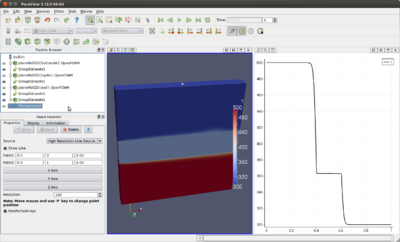
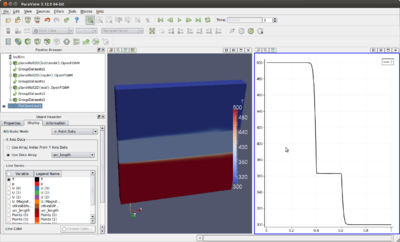
In the following two pictures is shown what you can do:
2.3 File description
The following list of files are the ones you should first pay attention when you want to reconfigure this case:
- 0/* - these are pre-configured and don't need to be modified... at least in theory.
- Allclean - this script is the one that takes care of reseting everything. Reconfigure it if you add more regions.
- Allrun - this script is the one that takes care of running the case. Reconfigure it if you add more regions and to suit your needs.
- constant - In this folder is placed all properties that are preserved during execution.
- polyMesh - In this folder is located the mesh for the case.
- blockMeshDict - This is the dictionary file used by blockMesh to generate the base mesh. It's here that you can change the base resolution of the mesh or even extend the dimensions of the mesh.
- regionProperties - This file defined which regions are solid and which are fluid.
- bottomAir - In here are defined all properties of the fluid located in the bottom region.
- topAir - In here are defined all properties of the fluid located in the top region.
- wall - In here is a single file that defines the properties of the solid.
- polyMesh - In this folder is located the mesh for the case.
- system - In here are the files that configure or help configure the case.
- controlDict - Here you control the number of iterations and so on...
- topoSetDict - Here you defined the extents of each region. It's here that you can select which cells of the mesh that belong in each region.
- bottomAir - In here are the runtime configurations for the bottom region.
- changeDictionaryDict - This is the main file where you define the actual boundary conditions to be used for the bottom region.
- topAir - In here are the runtime configurations for the top region.
- changeDictionaryDict - This is the main file where you define the actual boundary conditions to be used for the top region.
- wall - In here are the runtime configurations for the wall region.
- changeDictionaryDict - This is the main file where you define the actual boundary conditions to be used for the wall region.
3 Suggested Exercises
- Reduce the resolution of the mesh from 100x100x1 to 20x20x1 and use refineMesh to increase resolution where it matters, namely near the wall! A good reference tutorial for this is multiphase/cavitatingFoam/les/throttle.
- Change the properties of the solid and/or top and bottom fluids, so you can see what's going on.
- Extend the wall or apply the cyclic boundary condition to the outlets and inlets (the ones named leftLet and rightLeft), turning this into an infinite wall.
- Any more exercises are up to you!
4 References
- Maaike Van Der Tempel made a very useful tutorial about chtMultiRegionSimpleFoam for the MSc/PhD course in CFD with OpenSource software in 2012 at Chalmers University. Here is the quote for this particular project:
Maaike Van Der Tempel: A chtMultiRegionSimpleFoam tutorial. Slides Report Code Case1 Case2

