Difference between revisions of "Sig Turbomachinery / Timisoara Swirl Generator"
(→How to get the files) |
(→Descriptions of the scripts used in the cases) |
||
| Line 161: | Line 161: | ||
=== Descriptions of the scripts used in the cases === | === Descriptions of the scripts used in the cases === | ||
| + | |||
| + | '''Allrun''': Perform time-accurate ''transientSimpleDyMFoam'' analysis. | ||
| + | |||
| + | '''Allclear''': Remove time directories and return to the initial state. | ||
=== Check list in case of errors during the simulations === | === Check list in case of errors during the simulations === | ||
Revision as of 10:48, 7 June 2011
This page is under construction
Contents
1 Testcase description and experimental results
Håkan Nilsson, Chalmers University of Technology, Gothenburg, Sweden
Olivier Petit, Chalmers University of Technology, Gothenburg, Sweden
Petit et al. [1] provides a detailed description of the OpenFOAM case-study. The design of the geometry and experimental results are described thoroughly in [2-10]. The original test case was presented by Bosioc et al. [10] and was developed at Politehnica University of Tiisoara. The swirling test flow apparatus consists of four leaned strouts, 13 guide vanes, a free runner with 10 blades and a convergent divergent draft tube. The guide vanes create a tangentioal velocity component while keeping a quasi-constant presurs. The purpose of the free runner is to re-distribute the total pressure by inducing an excess in the axial velocity near the shroud and a corresponding deficit near the hub, like a Francis turbine operation at 70% partial discharge. The runner blades act like a turbine near the hub, and a pump near the shroud. Thus the runner spins freely, without any total torque. The design value for the rotation of the runner is 870 rpm, but stroboscope measurement on the test rige gives a slightly higher rotation, 920 rpm. The geometry is illustrated in Figure 1.
The measurements were performed at Politehnica University of Timisoara and were first presented by Bosioc et al. [10]. The flow rate was kept at 80% of the maximum power of the pum, that is 30 liter/s. The rotational speed of the free runner was 920 rm. Velocity coponenents have been measured in three different windows using with help of LDV (see Figure 2). The unsteady static presure is as well measured at four positions (see Figure 3) with help of Cole-Parmer unsteady pressure transducers.
 |
 |
 |
2 Published computational results
Muntean et al. [8] made a 3D numerical investigation of the viability of reducing pressure fluctuation of a precessing vortex rope by axial jet control in the discharge cone. Preliminary simulations were realized on the conical diffuser of the test rig [11], which showed that OpenFOAM gives as accurate results as commercial software. Petit et al. [1] made the first OpenFOAM simulations of the complete swirl generator, as a base for the OpenFOAM case-study. Those investigations were continued in a Master thesis project by Bergman [12].
Future publications that use this validation test case should refer to Petit et al. [1].
3 References
[1] Petit, O., Bosioc, A., Nilsson, H., Muntean, S., Susan-Resiga, R., A Swirl Generator Case Study for OpenFOAM, Submitted for publication in the proceedings of 25th IAHR Symposium on Hydraulic Machinery and Systems, 2010, Timisoara, Romania
[2] Susan-Resiga, R., Muntean, S., Bosioc, A., Stuparu, A., Milos, T., Baya, A., Bernad, S., and Anton, L.E., 2007, “Swirling Flow Apparatus and Test Rig for Flow Control in Hydraulic Turbines Discharge Cone”, in Proceedings 2nd IAHR International Meetings of the Workgroup in Cavitation and Dynamic Problems in Hydraulic Machinery and Systems, Scientific Bulletin of the Politehnica University of Timisoara, Transcations on Mechanics, Vol. 52(66), Fasc.6, pp. 203-216.
[3] Susan-Resiga, R., Muntean, S., Tanasa, C., and Bosioc, A., 2008, “Hydrodynamic Design and Analysis of a Swirling Flow Generator”, in Proceedings of the 4th German – Romanian Workshop on Turbomachinery Hydrodynamics (GRoWTH), June 12-15, 2008, Stuttgart, Germany.
[4] Bosioc, A., Susan-Resiga, R., and Muntean, S., 2008, “Design and Manufacturing of a Convergent-Divergent Test Section for Swirling Flow Apparatus”, in Proceedings of the 4th German – Romanian Workshop on Turbomachinery Hydrodynamics (GRoWTH), June 12-15, 2008, Stuttgart, Germany.
[5] Susan-Resiga, R., Muntean, S., and Bosioc, A., 2008, “Blade Design for Swirling Flow Generator”, in Proceedings of the 4th German – Romanian Workshop on Turbomachinery Hydrodynamics (GRoWTH), June 12-15, 2008, Stuttgart, Germany.
[6] Susan-Resiga, R., Vu, T.C., Muntean, S., Ciocan, G.D., and Nennemann, B., 2006, “Jet Control of the Draft Tube Vortex Rope in Francis Turbines at Partial Discharge”, in Proceedings of the 23rd IAHR Symposium on Hydraulic Machinery and Systems, Yokohama, Japan, Paper F192.
[7] Muntean, S., Susan-Resiga, R., Bosioc, A., Stuparu, A., Baya, A., Anton, L.E., 2008, “Mitigation of Pressure Fluctuation in a Conical Diffuser with Precessing Vortex Rope Using Axial Jet Control Method”, in Proceedings of the 24th IAHR Symposium on Hydraulic Machinery and Systems, Foz do Iguassu, Brazil.
[8] Muntean, S., Susan-Resiga, R., and Bosioc, A., 2009, “Numerical Investigation of the Jet Control Method for Swirling Flow with Precessing Vortex Rope”, in Proceedings of the 3rd IAHR International Meeting of the Workgroup on Cavitation and Dynamic Problem in Hydraulic Machinery and Systems, Brno, Czech Republic.
[9] Susan-Resiga, R., and Muntean, S., 2008, “Decelerated Swirling Flow Control in the Discharge Cone of Francise Turbines”, in Proceedings of the 4th International Symposium on Fluid Machinery and Fluid Engineering, Beijing, China. Paper IL-18.
[10] Bosioc, A., Susan-Resiga, R., and Muntean, S., 2009, “2D LDV Measurements od Swirling Slow in a Simplified Draft Tube”, in Proceedings of the CMFF.
[11] Muntean, S., Nilsson, H., and Susan-Resiga, R., 2009, “3D Numerical Analysis of the Unsteady Turbulent Swirling Flow in a Conical Diffuser Using Fluent and OPENFOAM”, in Proceedings of the 3rd IAHR International Meeting of the Workgroup on Cavitation and Dynamic Problem in Hydraulic Machinery and Systems, Brno, Czech Republic.
[12] Bergman, O. "", Master thesis, Chalmers University of Technology, 2010
4 Geometric data of the Timisoara Swirl Generator
The different parameters used in this case are showed below:
Operating conditions
Inlet Diameter 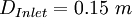
Throat radius 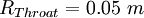
Throat velocity 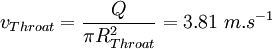
Rotational speed 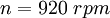
Flow rate coefficient 
Water density 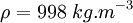
Inlet axial speed 
5 How to get the files
NOTE: NOT AVALIBLE YET!
The OpenFOAM Timisoara Swirl Generator cases described in the following sections were developed as a case-study for the Fifth OpenFOAM Workshop, Gothenburg, 2010, and can be found at the OpenFOAM-extend SourceForge project. It includes complete OpenFOAM cases that solve the flow in the domain and automatic post-processing of the results. The block-structured hexahedral mesh was generated in ICEM CFD, in four parts, which are coupled using GGI interfaces. The cases were developed using OpenFOAM-1.5-dev. Instructions on how to run the cases follow below.
Get all the current case files by doing:
 cd $FOAM_RUN
 svn checkout http://openfoam-extend.svn.sourceforge.net/svnroot/openfoam-extend/trunk/Breeder_1.5/OSIG/TurboMachinery/timisoaraSwirlGenerator
In the descriptions below, we thus assume that the timisoaraSwirlGenerator directory is located in the $FOAM_RUN directory
Update your files every now and then by doing:
 cd $FOAM_RUN/timisoaraSwirlGenerator
 svn update
See further info at OpenFOAM-extend webpage
The transientSimpleDyMFoam solver is used for this test case. To install and use it, see [ transientSimpleDyMFoam].
The turboPerformance functionObject is used to determine the shaft moment. To install and use it, see Sig Turbomachinery Library turboPerformance.
The trackDictionary functionObject is used as well. To install and use it, see trackDictionary.
6 Directory structure
The structure of the ercoftacCentrifugalPump directory is as follows:
TimisoaraSwirlGenerator
 |-- README
 |-- TSG
 |-- measurements
 |-- geometry
- The "geometry" directory contains the ICEM .tin files for the four different part of the test case: strout.tin, stayVanes.tin, runner.tin and draftTube.tin.
- The "measurements" directory contains the LDV data measured by Bosioc et al. [10] at the three availble windows in the draft tube. The data is re-arranged to facilitate the automatic post-processing.
- The case directory TSG ( for Timisoara Swirl Generator) contains the following files, scripts and directories:
README
setBatch
runScript.py
pythonScript/
system/
constant/
Allclear
Allrun
0.Orig/
transientSimpleDyMFoam.1/
7 Test cases
7.1 Descriptions of the scripts used in the cases
Allrun: Perform time-accurate transientSimpleDyMFoam analysis.
Allclear: Remove time directories and return to the initial state.