Difference between revisions of "TestHani"
(→Specific studies) |
(→A second base case, the BCD case) |
||
| Line 52: | Line 52: | ||
A second base case is defined similar as the case describe above, but only the geometry and grid between cross-sections B-D are used. The measured profiles at cross-section D are used as inlet boundary condition, and the outlet is located at the position where the diffuser ends into open air. | A second base case is defined similar as the case describe above, but only the geometry and grid between cross-sections B-D are used. The measured profiles at cross-section D are used as inlet boundary condition, and the outlet is located at the position where the diffuser ends into open air. | ||
| + | |||
| + | The case is located in the OpenFOAM-extend project at sourceForge. | ||
=== Contributed cases === | === Contributed cases === | ||
Revision as of 19:33, 13 January 2008
Contents
- 1 The ERCOFTAC diffuser case-study, geometry and base case set-up
- 2 Specific studies
- 2.1 Geometry and grid generation
- 2.2 Validation
- 2.3 Visualization
- 2.4 Boundary conditions
- 2.5 Turbulence models
- 2.6 Solver settings for fast computations
- 2.7 Parallel efficiency
- 2.8 Discretization schemes
- 2.9 Rotating frame of reference
- 2.10 Multiple frames of reference
- 2.11 Sliding grid
- 2.12 GGI interface
- 2.13 Other
1 The ERCOFTAC diffuser case-study, geometry and base case set-up
Maryse Page, Hydro Quebec, Montreal, Canada
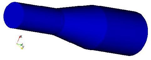
The ERCOFTAC diffuser [1] is an axi-symmetric expansion of a circular pipe, i.e. a conical diffuser. Figure 1 shows a 3D view of the geometry. The inlet is in this case located at the end of the honeycomb that was used in the experiments to generate a plug flow with a solid body rotation/swirl. An artificial extension of the domain has been added at the end of the expansion. In the experiments it was open air after the end of the expansion.
Figure 1. 3D view of the ERCOFTAC diffuser base case.
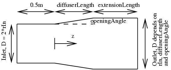
The OpenFOAM ERCOFTAC base case described below was developed as a case-study for the third OpenFOAM workshop, Milano, 2008, and it can be found at the OpenFOAM-extend SourceForge project. It includes a parametrization of the geometry and the O-grid, and a complete OpenFOAM case that solves the flow in the domain. The parametrization is made using m4, and instructions on how to run m4 are included in the case. Figure 2 shows the definitions of the parameters rIn, diffuserLength, extensionLength and openingAngle. It is thus easy to modify the geometry in terms of these parameters.
Figure 2. 2D view of the ERCOFTAC diffuser base case.
The grid generation in blockMesh is based on a number of cross-sections. It is easy to add or delete cross-sections in the m4 file if anyone would like to study another version of the same case. Figure 3 shows cross-sections A-G, that are used when making the mesh for the base case. The cross-sections refer to:
A: The outlet of the artificial extension, and the outlet of the computational domain.
B: The outlet of the diffuser.
C: The inlet of the diffuser.
D: A measurement plane.
E: The edge of a rotating part of the wall.
F: The edge of a rotating part of the wall.
G: The end of the honeycomb, and the inlet of the computational domain.
The number of cells in the z-direction between each cross-section is specified in the m4 file using parameters zABnumberOfCells (for the number of cells between cross-sections A and B), zBCnumberOfCells, etc.
Figure 3. Planes used in the parametrization.
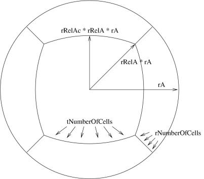
Figure 4 shows the parameters used for defining the O-grid throughout the domain. The figure is an example of the grid plane at cross-section A, but the parametrization at other planes are defined with parameters where 'A' is exchanged with the letter of the other cross-section. The number of cells in the radial direction in the O-grid is specified using parameter rNumberOfCells, and the number of cells in the tangential direction is specified using parameter tNumberOfCells (these must be integers!). The center block will thus get tNumberOfCells in both directions. These numbers are the same for all cross-sections. The grid point distribution of the center block, and thus in the tangential direction of the O-grid is uniform. The grid point distribution in the radial direction in the O-grid is defined using parameter rGrading, which is the same at all cross-sections. rGrading is the ratio between the size of the radially innermost cell in the O-grid to that of the outermost cell. That is how blockMesh generates non-uniform meshes.
The location of cross-section A in the z-direction is specified using parameter zA. The outer radius of cross-section A is specified using parameter rA. The radius of the vertices of the center block, relative to rA, is specified using the parameter rRelA, which should be between 0 and 1. In other words, the radius of the vertices may be anything from 0 (rRelA = 0, but that would make no sense) to rA (rRelA = 1). The radius of the center point of each edge of the center block is specified relative to the radius of the vertices of the center block. The edge between two vertices is thus an arc with a center radius of rRelAc * rRelA * rA. rRelAc should be between 0 and 1, where 1 gives a center block with circular edges. These definitions make it easy to modify the O-grid thickness relative to the outer radius, while keeping a high quality shape of the O-grid.
Figure 4. O-grid used in the parametrization.
1.1 A second base case, the BCD case
A second base case is defined similar as the case describe above, but only the geometry and grid between cross-sections B-D are used. The measured profiles at cross-section D are used as inlet boundary condition, and the outlet is located at the position where the diffuser ends into open air.
The case is located in the OpenFOAM-extend project at sourceForge.
1.2 Contributed cases
Here you can add sections with case definitions that are of general interest, or that is needed for discussions in the sections below. Keep the Wiki nice and tidy! Co-organize your case definitions with those from other contributors!
1.3 References
[1] P.D. Clausen, S.G. Koh and D.H. Wood. Measurements of a swirling turbulent boundary layer developing in a conical diffuser. Experimental Thermal and Fluid Science, 6:39-48, 1993
2 Specific studies
Here you can add your conclusions from your own studies of this case. Keep the Wiki nice and tidy! Co-organize your conclusions with those from other contributors!
2.1 Geometry and grid generation
Recommended settings of the parametrization. Recommended geometry. Discussions about the artificial extension, and how to treat the outlet into open air.
2.2 Validation
Validations against measurements. Development of implementations for automatic extraction and plotting.
2.3 Visualization
Development of implementations for automatic visualization of the results.
2.4 Boundary conditions
Discussions on different boundary conditions and different implementations. Comparisons, verifications, validations.
2.4.1 Inlet
2.4.2 Walls
2.4.2.1 Stationary
2.4.2.2 Rotating
2.4.3 Outlet
2.5 Turbulence models
2.6 Solver settings for fast computations
It is always of interest to increase the computational speed, and the stability of the simulations... But it is of also of interest that the different settings give accurate results.
2.7 Parallel efficiency
Comparisons using different hardware configurations.
Scripts for automatic scaling tests.
2.8 Discretization schemes
Studies of the influence of different discretization schemes
2.9 Rotating frame of reference
Do you get the same results in a rotating frame of reference?
2.10 Multiple frames of reference
Even if it is not necessary for ths case, it is possible to verify the concept of Multiple Frames of Reference assuming that some parts of the domain is rotating while other aren't.
2.11 Sliding grid
See above
2.12 GGI interface
See above
2.13 Other
Please come with more ideas...


